
Page 2


CHAPTER 3
BASE ISOLATION TECHNIQUES
In traditional seismic design approach, strength of the structure is suitably adjusted to resist the earthquake forces. In base isolation technique approach, the structure is essentially decoupled from earthquake ground motions by providing separate isolation devices between the base of the structure and its foundation. The main purpose of the base isolation device is to attenuate the horizontal acceleration transmitted to the superstructure. All the base isolation systems have certain features in common. They have flexibility and energy absorbing capacity. The main concept of base isolation is to shift the fundamental period of the structure out of the range of dominant earthquake energy frequencies and increasing the energy absorbing capability.
Presently base isolation techniques are mainly categorized into three types viz. Passive base isolation techniques, Hybrid isolation with semi-active devices and Hybrid base isolation with passive energy dissipaters. These different techniques are discussed in short below –
3.1. Passive base isolation techniques
Various passive base isolation techniques are,
3.1.1 Mud layer below the structure
Frank Lloyed Wright was the first person who implemented the idea of base isolation technique for isolating Imperial Hotel structure in Tokyo, by providing closely spaced short length piles in 8 feet thick soil layer underlain by a thickness of mud layer over hard strata. The building survived an earthquake in 1923.
3.1.2. Flexible first storey
The flexible first storey concept was first proposed by Martel in 1929 and was further studied by Green in 1935 and Jecobson in 1938 thereby reduce the loading on upper storey members. However, further studies by Chopra et. al.with the aid of computers showed that the concept is impractical. Also the recent earthquakes at Bhuj in India and Kobe in Japan have revealed that most of the buildings with soft storey have suffered extensive damage.
3.1.3. Roller bearings in foundations
Roller bearing systems proposed for isolation of the structures were having serious drawback as the rollers were having to and fro motion in particular direction and earthquake has three directions motion due to which earthquake forces could not be isolated effectively. Also the main problem was that the device needed maintenance for keeping in good operation throughout its working life period. The system was further modified with ball bearing system.
3.1.4. Rubber layer as foundation support
School building in Skopje, Yugoslavia constructed on rubber foundations in 1969, used to bounce and rock forward and backward during earthquake due to uniform stiffness of rubber in all directions. Also the rubber foundation bulged under the weight of the building.
3.1.5. Laminated rubber bearing system
Laminated rubber bearings (LRB) (ref. Fig.3.1), which are made of thin layers of steel plates and rubber built in layers one over the other, have horizontal flexibility, high vertical stiffness and they can be characterized by natural frequency and damping constant.
The main advantages of rubber bearing system are -
• Effective isolation is achieved. It will decrease the structural response to 1/2 -1/8 of the traditional structural response.
• Stable character of isolators over a long working life
• Recovery of the displacement after earthquakes
• Vertical tension capacity is good
• Isolators are insensitive for foundation settlement, which are generally small in magnitude. It could adjust the structure force by deformation of rubber bearings when foundation settlement of building happens before or after earthquakes
• Decreasing the temperature stress in structures by free horizontal deformation of bearings during large change of temperature around the structure

Fig.3.1. Laminated rubber bearing system - a) Sectional details b) Schematic diagram c) Force deformation behavior (source: S. J. Patil, G. R. Reddy Website: www.ijetae.com)
3.1.6 New Zealand bearing system
The system (ref. Fig.3.2), invented in NewZealand in the year 1975, is improved version of laminated rubber bearing wherein a centrally located lead core is introduced, which has energy dissipating capacity. The presence of lead core reduces displacement of the isolator and isolator essentially works as hysteretic damper device. The device has been extensively used in New Zealand, Japan and USA. Buildings isolated with these devices performed well during the 1994 North ridge earthquake and 1995 Kobe earthquake.

Fig. 3.2. New Zealand bearing system (a) Sectional details (b) Schematic diagram (c) Force deformation behavior (source: S. J. Patil, G. R. Reddy Website: www.ijetae.com )
3.1.7. Resilient – friction base isolation system
Resilient – Friction Base Isolation (R-FBI) system (ref. Fig.3.3) proposed by Mostaghel and Khodaverdian consists of concentric layers of Teflon coated plates which will have sliding resistance and a central core of rubber which will have beneficial effect of resilience of a rubber.
3.1.8. Electric de-France system
Electric De-France (EDF) (ref. Fig. 3.4) system is friction type base isolation system developed under the auspices of Electric de France in the year 1970. The system is standardized for Nuclear power plants in the region of high seismicity. The system consists of laminated Neoprene pad topped by a lead bronze plate, which is in frictional contact with steel plate anchored to the base raft of the structure. Therefore its cross section is similar to the LRB system.
The neoprene pad has very low displacement capacity (5 cm approx.) and when this capacity is exceeded, the sliding element provides the needed movement. The system does not include any restoring device and hence permanent displacement could occur. The system has been implemented in nuclear power plant at Koeberg in South Africa.

Fig. 3.3. Resilient – friction base
a) Sectional details
b) Schematic diagram
c) Force deformation behavior
Fig 3.4. Electric De-France (EDF) isolation system
(a)Schematic diagram
(b)Force deformation behavior
(source: S. J. Patil, G. R. Reddy Website: www.ijetae.com)
3.1.9. Sliding resilient- friction system
The design of sliding resilient- friction base isolator (refer fig. 3.5) was proposed by Su et. al. This isolator is combination of good features of EDF and R-FBI systems. The upper surface of the R-FBI system is replaced with friction plates. As a result the structure can slide on its foundation in a manner similar to that of the EDF base isolator system. For a low level of seismic excitation, the system behaves as an R-FBI system. The sliding in the top plates occurs only during high level of ground acceleration, which provides additional safety against unexpected severe ground motion.
3.1.10. High damping rubber bearing
A blend of high damping rubber is used in these bearings (ref. Fig. 3.6). The compound, a high damping elastomer, is called KL301 and is manufactured by the Bridgestone Corporation Limited, Japan. KL301 has a shear modulus of about 4300 kPa at very small strains, which decreases to 650 kPa at 50% strain, to 430 kPa at 100% strain and 340 kPa at 150% strain. The typical bearing made of this rubber, consists of 20 layers of 2.2 mm thick rubber at 176 mm dia, nineteen 1mm steel shims, and 12 mm top and bottom plates. The design axial pressure is 3.23 MPa. The bearings were designed with flange type end plates to provide bolted structure and foundation connection.

Fig 3.5. Sliding resilient friction system
(a) Schematic diagram
b) Force deformation behavior
Fig 3.6. High damping rubber bearing
(a) Sectional details
(b) Forcedeformation behavior
(source:S.J.Patil, G.R.Reddy Website: www.ijetae.com)
3.1.11. Pure friction system
A pure friction type base isolator consists of developing frictional force by providing a sand layer or rollers at the base, which will dissipate the energy of earthquake force. The system is developed in China for low-rise structures. The system is useful for wide range of frequency input.
The main advantage of this isolation device is that it is very cheap. The main problem with the system is that it is unable to recover the displacement after earthquakes and sand layer is very sensitive for foundation settlement.
3.1.12. Friction pendulum system
Friction pendulum system (ref. Fig. 3.7) uses geometry and gravity to achieve the desired seismic isolation. It is based on well-known engineering principles of pendulum motion. The structure supported by the FPS responds to the earthquake motions with small pendulum motions. The friction damping absorbs the earthquake energy. There are variety of friction pendulum system developed by various researchers such as, variable frequency pendulum isolators by Pranesh & Sinha, 2000, variable curvature pendulum systems by Tsai et al, 2003, sliding concave foundation by Hamidi et al., 2003, double concave friction pendulum system by Fenz and Constantinou, 2006, Triple friction pendulum bearing, Fenz and Constantinou, 2008. Friction pendulum system is very efficient and cost effective seismic protection device, which simply alter the force response characteristics of the structure at base isolation level.

Fig 3.7. Friction Pendulum Base Isolator
(a) Friction pendulum system
(b) Roller pendulum system
(Source: S. J. Patil, G. R. Reddy Website: www.ijetae.com)
3.1.13. Spring type systems
Elastomeric and sliding isolation systems are effective in isolating the structure from horizontal forces. When three dimensional isolation is required, spring type systems have been used. The spring type system under the brand name of GERB was developed with large helical steel springs having flexibility both in horizontal and vertical direction. The vertical frequency of the system was 3 - 5 times the horizontal frequency. The steel springs were used with GERB visco damper.
The system has been used in two steel framed houses in Santa Monica, California. These houses were strongly affected by the 1994 Northridge earthquake. The response of these buildings was monitored and it was not effective in reducing the accelerations in these buildings due to rocking motion.
3.1.14. Sleeved pile isolation system
Where foundation soil is very soft up to large depths and provision of pile foundation is necessary, sleeved pile isolation system is useful from earthquake considerations. The system consists of providing a casing around the pile and a gap is maintained between the pile and the casing to accommodate the sway of the pile under earthquake load. The pile is passed through the soft soil and is supported and anchored in the rock below.
This system was implemented in the Union house in Auckland, New Zealand in the year 1983. The building is 12 storeyed tall and is supported on piles through soft soil for depth of 10m enclosed in steel casing. The period of the building on the sleeved pile system is 4 seconds.
3.1.15. Rocking systems
Tall slender structures, having heavy mass at the top, will invariably develop overturning moments which will lead to development of tensions in the foundations. It is extremely difficult to provide tension capacity in the foundations when foundations are in weak soil and providing anchors is a costly affair. As a remedy to this problem, it is possible to allow lifting of columns or piers from the foundation. This type of partial isolation will reduce the earthquake loads throughout the structure.
This concept was implemented in a railway bridge on south Rangitikei river in New Zealand in the year 1972. It has 69m long pier, which has been designed to lift under the earthquake load. Two large energy dissipating devices that are based on the elastic-plastic torsion of mild steel bars have been provided inside each pier. The method is not used again probably due to complexities involved in analysis and design of the system.
3.1.16. Base isolation using Geo- Synthetic materials
M.K. Yegian and U. Kadakal have developed a technique of isolating the base of the structures using geo-synthetic material. They have used high strength, non woven geotextile placed over an ultra high molecular weight polyethelene (UHMWPE) liner. These two materials have a static friction co-efficient of 0.1 and a dynamic friction coefficient of 0.07. Thus a geo-synthetic material placed underneath a foundation of a structure and over a liner will allow the dissipation of earthquake energy in sliding friction. They suggested that the sliding friction between the two materials should be in the range of 0.05 to 0.15. The authors have suggested arrangements as shown in fig 9 except the energy dissipating devices.
3.1.17. BS cushion
In 1999 a new kind of base isolator called BS cushion was invented (Chinese Patent Number ZL99202381.5) in Hangzhou, China. It is Treated Asphalt-Fiber Seismic Base Isolation Cushion”. The advantage of this kind of isolator is its low cost and safety while its isolation effect is moderate.
The invention of BS cushion reminds laminated steel-plate rubber bearing. Fiber and treated asphalt in BS cushion play similar role as of steel-plate and rubber in laminated rubber bearing respectively. Before 2001 two 7-storey masonry-concrete residential buildings isolated with BS cushion were built in Hangzhou, China. One is isolated by replacing some depth of base soil under mattress foundation with alternative setting of 4 layers of BS cushion and 4 layers of sand. The fundamental period of this building is elongated from 0.3 second to 1 second (0.3s is tested from a similar building and 1s is tested from this building).
3.2. Hybrid isolation system with semi-active devices
Hybrid isolation system uses both passive isolation systems and semi-active / active controlling devices. The Medical Centre of the Italian Navy at Ancona, Italy, was selected with the aim of analyzing the behavior of a hybrid system composed by Low Damping Rubber Bearings (LDRBs) acting as passive seismic isolators, and Magneto-rheological (MR) dampers, acting as semi-active controlling devices. The analyses showed that significant reduction of the building accelerations (up to 50%) can be achieved with the hybrid system.
3.3. Hybrid base isolation with passive energy dissipaters
` The energy dissipating devices (ref. Fig. 9 to 16) mainly dissipate the earthquake energy and thereby reduce the effect of the earthquake on the structure. These devices can be used at the base of the structure or in superstructure at appropriate locations. They can be used in combination with passive base isolation techniques. The different devices developed world over are shown in Fig. 3.8 to 3.13.

Fig. 3.8. Use of energy dissipating devices at base level
(Source: S. J.Patil, G. R. Reddy Website: www.ijetae.com)
Structure responses can be controlled by using Visco- Elastic dampers (VEDs), which are made of linear springs and dash pots provided in parallel and are generally used in bracings of building frame or at ground level.

Fig.3.9.Visco - Elastic Damper
(Source: S. J.Patil, G. R. Reddy Website: www.ijetae.com)
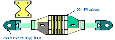
Elasto-Plastic Dampers (EPDs) are made of number of small ‘X’ shaped plates, which yield at small deformation thereby dissipate high amount of energy.

Fig. 3.10.Elasto-plastic damper
(Source: S. J. Patil, G. R. Reddy Website: www.ijetae.com)
Lead Extrusion dampers (LEDs) work on the principle of extrusion of lead. It absorbs vibration energy by plastic deformation of the lead, during which mechanical energy is converted into heat, lead gets heated up and on being extruded, lead re-crystallizes immediately and recovers its original mechanical properties before next extrusion

Fig. 3.11. Lead Extrusion damper
(Source: S. J. Patil, G. R. Reddy Website: www.ijetae.com)
Tuned Liquid dampers (TLDs) are rigid wall containers filled up to required height with a liquid (generally water) to match the sloshing frequency of the liquid with that of the structure. These containers are generally placed on the top of the structure. The vibration energy is dissipated in the sloshing action of the liquid.
Fig.3.12. Tuned liquid damper
(Source: S. J. Patil, G. R. Reddy Website: www.ijetae.com)
Shape Memory Alloy Dampers (SMADs) made of nickel-titanium (Ni-Ti) alloy wires has an interesting pseudo-elastic property by which the alloy regains its initial shape when external load is removed. This property is useful in putting back the structure to its original shape. Also it can sustain large amount of inelastic deformation.
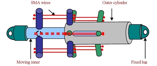
Fig. 3.13. SMA damper
(Source: S. J. Patil, G. R. Reddy Website: www.ijetae.com)
An un-bonded brace, a technique developed in Japan, consists of developing a brace which is prevented from buckling by way of providing a metal collar filled with concrete at the center of brace and a thin layer of viscous material which allows slip and Poisson’s ratio expansion at the slip surface provide relative movement between the steel collar and surrounding concrete. This protects the brace from buckling and allows proper dissipation of energy in the brace through stable hysteresis loop. A buckling restrained or core loaded or non-buckling brace developed in IIT, Madras also works on the similar lines and dissipates the earthquake energy.
Tuned Mass Damper (TMD) is a spring – mass damper device generally connected to the structure at its top. It has been used as a passive control device for response reduction of tall buildings.
Examples Of Isolated Structures In Different Countries –
Few examples of isolated structures are William Clayton building, New Zealand, Medical Centre of the Italian Navy (Sarvesh K. Jain And Shashi K. Thakkar, 2004, LRB+MRD system), Nam-Han River bridge on the Young-dong expressway Seoul, Korea (Sun Young Lee, et al., 2004, LDRB+MRD system), Experimental building at IIT, Guwahati, India [8] etc.
The number of seismically isolated buildings in Japan, Russia, China, USA, Italy, Armenia, New Zealand were 1600, 500, 458, 100, 27, 14 and 11 respectively up to December 2002, 2003 and every year the number of isolated structures are increasing.
PAGE


No comments:
Post a Comment