
1. INTRODUCTION
Natural disaster is a hot issue
in international society and academy. The term "tropical cyclone" is
a generic name used to refer to all organized, circulating weather systems of
low pressure that develop over tropical waters. Tropical cyclone is perhaps the
most devastative natural disasters both because of the loss of human life they
cause and the large economic losses they induce. On an average, 80-100 tropical
cyclones happen over the world and they cause 20,000 deaths and the economic
losses worth 7 billion dollars per year. The vulnerability to tropical cyclones
is becoming more pronounced because of the fastest population growth in
tropical and subtropical coastal regions.
The vulnerability of a human settlement to a
cyclone is determined by its siting, the probability that a cyclone will occur,
and the degree to which its structures can be damaged by it. Buildings are
considered vulnerable if they cannot withstand the forces of high winds.
Generally those most vulnerable to cyclones are lightweight structures with
wood frames, especially older buildings where wood has deteriorated and
weakened the walls. Houses made of unreinforced or poorly-constructed concrete
block are also vulnerable. Urban and rural communities on low islands or in
unprotected, low-lying coastal areas or river floodplains are considered
vulnerable to cyclones. Furthermore, the degree of exposure of land and
buildings will affect the velocity of the cyclone wind at ground level, with
open country, seashore areas and rolling plains being the most vulnerable. The
destructive force of typhoon is strong and great harmful, and the typhoon often brings heavy rains, storm surges, river
floods and flash floods in small basins and mud-rock flows, landslides and
other disasters. More than 95% of the flood disasters caused due to the impact
of typhoon, which threat seriously to the people's personal safety and
property.
Disaster is merciless. And it is important to
guard against disaster. Therefore, in the process of formulating the overall
construction planning of villages and towns, disaster prevention and mitigation
planning should be strengthened, based on local species vulnerable to the
disaster and their characteristics.
2. CYCLONE
Cyclones
are vortices in the atmosphere having a core called the eye of extreme low
pressure and light winds, surrounded by strong winds having nearly circular
contours of equal pressure called isobars. They produce very strong winds rotating clockwise around a calm
centre. Very strong winds, heavy rainfall with flooding and storm tide are all
elements of a tropical cyclone. Strong winds generated during severe tropical
cyclones can cause extensive property damage and turn wind-borne debris into
missiles. Tropical cyclones can also produce heavy rainfall over extensive
areas that can cause further damage to property and infrastructure and potential
injury and loss of life. As well, the low central pressure and strong winds
over the ocean can lift the sea water surface to produce a storm tide
The radial distance from the centre of the eye
to the region where the maximum tangential wind velocity occurs is called the
radius of maximum winds (RMW). The wind speed falls off gradually beyond this
region and the approximate wind velocity distribution is given by:

where
V(r)
|
=
|
velocity of wind at a radial distance, r;
|
ro
|
=
|
radius of maximum wind (RMW);
|
Vo
|
=
|
velocity of maximum wind; and
|
Α
|
=
|
a power law exponent varying between 0.4 to 0.6.
|
NOTE—r and ro are to be measured
from the centre of the eye of the storm.
|
||
In
the interior region to the radius of maximum wind the velocity distribution may
be assumed as linear varying from zero at centre of eye.
2.1 CATEGORIES OF CYCLONES
This five-category system is based on the wind
speeds generated by the
cyclone. The Bureau of Meteorology quotes wind speeds measured under standard conditions – at a height of
10m above the ground and measured in flat, open terrain. The
following table presents maximum expected sustained winds and estimated wind
gusts near the centre of a tropical cyclone measured under standard conditions.
The Bureau of Meteorology uses a 10 minute averaging time for
reporting the sustained winds.
Table 2.1
categories of cyclones
Cyclone
category
|
Estimated
sustained wind
speeds
(km/hr)
|
Name
|
Strongest
gust
(km/hr)
|
Typical effect
(indicative
only)
|
1
|
63-88
|
Tropical
cyclone
|
Below 125
|
Tropical cyclone causing negligible house damage. Damage to
some crops, trees and caravans. Watercraft may drag moorings.
|
2
|
89-117
|
Severe
Cyclonic Storm (SCS)
|
125-164
|
Cyclone causing minor house damage. Significant damage to
signs, trees and caravans. Heavy damage to some crops. Risk of power failure.
Small watercraft may break moorings.
|
3
|
118-159
|
Very
SCS
|
165-224
|
Cyclone causing some damage to roofs and structural damage on
older houses. Some caravans destroyed. Power failure likely.
|
4
|
160-199
|
Very
SCS
|
225-280
|
Cyclone causing significant roofing loss and structural damage
on older houses. Many caravans destroyed and blown away. Dangerous Air borne
debris.Widespread power failures.
|
5
|
Over 200
|
Super
Cyclonic Storm
|
Above 280
|
Extremely dangerous with potential for wide spread destruction.
|
2.2 BASIC
WIND SPEED ZONES
The macro-level wind speed zones of India have been formulated and
published in IS: 875 (parts) - 1987 titled " Indian Standard Code of
Practice for Design Loads (other than earthquakes) for Building and Structures,
Part 3, Wind Loads". There are six basic wind speeds ‘V0’
considered for zoning, namely 55, 50, 47, 44, 39 and 33 m/s. From wind damage
viewpoint, these could be described as follows:
55 m/s (198 km/h) - Very High Damage Risk Zone - A
50 m/s (180 km/h) - Very High Damage Risk Zone - B
47 m/s (169.2 km/h) - High Damage Risk Zone
44 m/s (158.4 km/h) - Moderate Damage Risk Zone - A
39 m/s (140.4 km/h) - Moderate Damage Risk Zone - B
33 m/s (118.8 km/h) - Low Damage Risk Zone
The basic wind speeds are applicable to 10 m height above mean ground
level in an open terrain with a return period of 50 years. At higher elevations
and longer return periods, the values will be higher.
The earlier wind pressure maps (one giving winds of shorter
duration and other excluding winds of shorter duration) were replaced by a
single wind map giving basic maximum wind speed in m/s (peak gust speed
averaged over a short time interval of about 3 seconds duration). The wind
speeds were worked out for 50 years return period based on the up-to-date wind
data of 43 dines pressure tube (DPT) anemograph stations and study of other
related works available on the subject since 1964.

Fig.2.2
Basic wind speed in m/s (based on 50 year return period)
2.3 Kerala-an over view
Kerala
is relatively safe from coastal cyclones, going by the database on cyclones.
The State has been included in Lower Vulnerability Zone along with Tamil Nadu,
Maharashtra, Goa, Karnataka, Daman and Diu, Pondicherry, Lakshadweep, and
Andaman and Nicobar Islands. The Kerala region, in general, has lesser
probability of getting affected by the occurrence of cyclonic storm or severe
cyclonic storm, according to the report. Though relatively safe from coastal
cyclones, there have been instances of localised coastal cyclones and speedy
winds following water spouts.
3. THE QUALITY AND SAFETY
PROBLEMS OF RURAL HOUSING PROJECTS
"The
typhoon disaster" is essentially due to the insufficient strength of
house. The 'self-collapse' result from
the unreliable connection of the various components of house, poor quality of
anchors, and no attention paid to resisting wind. It should be noted that the
determinants of anti-typhoon capacity of house are the stiffness and integrity
of whole house and not entirely dependent on wall thickness or all of the use
of reinforced concrete. The
better the integrity, the greater the stiffness is. The greater the stiffness,
the stronger the wind- resistance is. The quality and safety of rural building
problems are as follow:
3.1 BAD CONSTRUCTION QUALITY:
Most of the rural houses are of brick buildings and most of them are
constructed by masons. The poor construction quality has affected the housing
integrity and weakened the housing stiffness, wind-resistance and lateral
displacement resistance, which result in insufficient capacity of residential housing
.
3.2 IRRATIONAL STRUCTURE:
Most of the houses collapsed in typhoon are of simple structure, such as wood
structure, brick-wood structure and so on. Housing Constructions do not set
constructional column, which is deadly to the affected houses. To set
constructional column is important for improving house anti-collapse ability
House with large open windows and doors, are also contributed to the collapse
of buildings in typhoon. After wind damages large doors and windows, the air
flow directly acts on the lower part of the roof, which cause the roof damage,
water penetrated the wall, so that the wall capacity declined.
3.3 SUB-STANDARD BUILDING
MATERIALS: Money spent on the construction of houses is
farmer's hard-earned money. villagers spend money as little as possible on
building a new house, which leave them potential hazard. Some villagers have
not enough money to whitewash the external walls, and the walls suffer from prolonged
exposure to rain erosion, which reduce the bearing capacity of the walls.
Although some houses adopt cement mortar or cement lime mortar, in which there
are low cement content, impurities, leading to a low strength of cement sand
mortar.
4. TYPES OF DAMAGE DURING CYCLONES
As a consequence
of the wind pressures/suctions acting on elements obstructing the passage of
wind the following types of damage are commonly seen to occur during high wind
speeds:
·
Uprooting of trees, which disrupt rail and road transportation;
·
Failures of many cantilever structures such as sign posts, electric
poles, and transmission line towers;
·
Damage to improperly attached windows or window frames;
·
Damage to roof projections and sunshades;
·
Failure of improperly attached or constructed parapets;
·
Overturning failures of compound walls of various types;
·
Failure of weakly built walls;
·
Failure of roofs and roof covering-This
is perhaps the commonest area of failure in cyclones. The causes are usually
inadequate fastening devices, inadequate sheet thickness and insufficient
frequencies of fasteners in the known areas of greater wind suction.

Fig 4.1 Loss of corrugated metal, roof sheets
·
Failure of large industrial buildings with light weight roof coverings
and long/ tall walls due to combination of internal and external pressures;
·
Brittle failure of asbestos - cement (AC) sheeting of the roofs of
Industrial sheds; failure of AC sheets is generally along eaves, ridges, and
gable ends;
·
Punching and blowing off of corrugated iron roofing sheets attached to
steel trusses;
·
Foundations-The
uplift forces from cyclone winds can sometimes pull buildings completely out of
the ground.


Fig 4.2 Foundation pulled completely out of ground
·
Steel frames: Usually
the weakness in steel frames is in the connections. Economizing on minor items
(bolts) has led to the overall failure of the major items (columns, beams and
rafters).
·
Timber
House: The
inherent vulnerability of light-weight timber houses coupled with poor connections
is a dangerous combination which has often led to disaster.
·
Rafters-Of
particular interest in recent cyclones was the longitudinal splitting of
rafters with the top halves disappearing and leaving the bottom halves in
place. The splitting would propagate from holes drilled horizontally through
the rafters to receive holding-down straps.
Table 4.1
shows the aerofoil effects of some cyclonic wind speeds.
Table 4.1:
Aerofoil Effect of Wind
Wind
Speed, m/sec.
|
Typical
Possible Movement
|
30-35.1
|
Roof sheets fixed to battens
fly
|
35-40
|
Small aircrafts take off
speed
|
40-45
|
Roof tiles nailed to battens
fly
|
45-50
|
Garden walls blow over
|
50-55
|
Unreinforced brick walls
fail
|
55-60
|
Major damage from flying
debris
|
60-65
|
75 mm thick concrete slabs
fly
|
Given
below are some typical effects of openings in the walls from the attack of
winds as well as the pressure on each of the building components:-
•
Wind generating opening on
the windward side during a cyclone will increase the pressure on the internal
surfaces. This pressure, in combination with the external suction, may be
sufficient to cause the roof
to blow off and the walls to explode.

Fig 4.3 Blow off of roofs due to wind generating opening
•
Another mode of failure
occurs when the windward side of the house collapses under the pressure of the
wind.

Fig 4.4 Windward face of
the building collapses under pressure
of wind force
•
During a cyclone an opening
may suddenly occur on the windward side of the house. The internal pressure
which builds up as a result may be relieved by providing a corresponding
opening on the leeward side.

Fig 4.5 Opening on the leeward side due to internal
pressure
•
If
the building is not securely tired to its foundations, and the walls cannot
resist push/pull forces the house tends to collapse starting the roof with the
building leaning in the direction of the wind.


Fig 4.6 Collapse start at the roof building leaning
in the wind direction
•
Failure
of the Wall: Wind forces on the walls of the house may
produce failure. Wind striking a building produces pressure which pushes
against the building, on the windward side, and suction which pulls the
building on the leeward side and the roof. If no air enters the building, then
there is pressure inside which is pushing against the walls and the roof.

Fig 4.7 wall failure
•
Overturning is another
problem for light structures. This occurs when the weight of the house is
insufficient to resist the tendency the house to be blown over.

Fig 4.8 Overturning of light structures
5. DESIGN WIND SPEED AND
PRESSURES OF BUILDINGS
5.1 WIND SPEED
The basic wind speed is reduced or
enhanced for design of buildings and structures due to following factors:
(i) The risk level of the structure measured in terms of adopted return
period and life of structures (5,25,50 or 100 years),
(ii) Terrain roughness determined
by the surrounding buildings or trees and, height and size of the structure.
(iii)
Local topography like hills, valleys, cliffs, or ridges, etc.
(iv) Importance factor for the cyclonic region.
Thus general basic wind speed being the same in a given zone,
structures in different site conditions could have appreciable modification and
must be considered in determining design wind velocity as per IS: 875 (Part 3)
- 1987.
It
is known that higher wind speed occurs during cyclones compared to non-cyclonic
storms. Further, there is a greater degree of turbulence in such storms and the
probability of occurrence during the life time of a structure is also large.
Therefore, structures are subjected to greater risk under cyclonic storms. To
account for the enhanced risk, an importance factor ‘k4’, whose value is equal to unity for dwellings, 1.15
for industrial buildings, and 1.30 for structures of post-cyclone, importance
shall be considered while determining the design wind speed. The design wind
speed Vz at any height z in m/s shall be taken as:
Vz = Vb k1 k2 k3 k4,
where
Vz = design
wind speed at any height z in m/s,
Vb = basic wind speed
k1 = probability
factor (risk coefficient)
k2 = terrain
roughness and height factor
k3 = topography
factor and k4 = importance factor for the
cyclonic region;
The values of k1, k2,
k3, and Vb shall be as specified in IS 875
(Part 3).
5.2 WIND PRESSURE
The wind pressure at any height above mean ground level shall be
obtained by the following relationship between wind pressure and wind speed:
Pz = 0.0006 Vz2
Where,
Vz = design wind
velocity, m/s
Pz
= design wind pressure, kN/m2
The design wind pressure pd can be obtained as,
pd = Kd. Ka. Kc. pz
where
Kd = Wind directionality factor
Ka = Area averaging
factor
Kc = Combination factor
The
value of wind pressure actually to be considered on various elements depends on
(i)
Aerodynamics of flow around buildings.
(ii)
The windward vertical faces being subjected to pressure.
(iii)
The leeward and lateral faces getting suction effects and
(iv)The
sloping roofs getting pressures or suction effects depending on the slope. The
projecting window shades, roof projections at eave levels are subjected to
uplift pressures. These factors play an important role in determining the
vulnerability of given building types in given wind speed zones.Figure5.2.1 shows the various cladding areas of a building, which will
have different pressure coefficients.

Fig.5.2.1 External wind pressure
areas on building faces
Figures 5.2.2(a) and 5.2.3(b) show typical effects of openings in the
walls for a given angle of attack of wind as indicated:
(a) Only one large opening in a wall will cause very large internal
pressure say 0.7Pz.which combined with external pressures/suctions
will modify the wind effects on cladding and their connections immensely.
(b) A
building with all windows and doors locked will have zero or very small
internal suction or pressure, 0.2 Pz. If a room has openings
distributed in all walls or at least in opposite walls and the overall porosity
is less than 5%, the passage of air will cause only low internal pressure say
only 0.2 Pz. Effects of wind uplift on roof projections can also be
seen in Fig.5.2.2(a), (b). For a design speed of 50 m/ s, the basic pressure
will be 1.5 kN/m2 and the design pressure could be obtained by
multiplying with the coefficients given in Fig. 3 (a) and (b) for the specimen
cases shown. For other dimensions of length, width and height and direction of
wind, reference may be made to IS: 875 Part 3-1987.


Fig.5.2.2 Structural Load
Coefficients, Internal and External Pressures
5.3
COASTAL AREAS
The coastal areas are subjected to severe windstorms and cyclonic
storms. It is known that in certain events, the wind gusts could appreciably
exceed the specified basic wind speeds (by as much as 40 to 55%). But for
design of structures (except those considered very important) the above macro-level
zoning stated in 2.2 is considered as sufficient. The frequency of occurrence
of cyclones on the different portions of the coast has been different.
5.4 STORM SURGE
Besides the very high velocity winds, the coastal areas suffer from the
onslaught of seawater over the coast due to storm surge generated by cyclones.
A storm surge is the sudden abnormal rise in sea level caused by the cyclone.
The surge is generated due to interaction of air, sea and land. The seawater
flows across the coast as well as inland and then recedes back to the sea. Huge
loss of life and property takes place in the process. The height of the storm
surge is even higher during the period of high tides.
6. PLANNING ASPECTS
6.1 BASIC REQUIRMENT OF CYCLONE
RESISTANT BUILDINGS
Based
on the above facts the housing plan, design and executions should be carried
out
considering
the following.
·
Avoid a low pitched roof
·
Use of Hip roof (or) High
Pitched gable roof
·
Avoid over hanging roofs.
·
Cyclone shutters to be
introduced in the opening places.
·
Minimize the projection of
eaves.
·
Recommended steel
reinforcement should be provided in the wall as seismic band in vertical and
horizontal directions.
·
The foundation of the
building should be designed by taking bearing capacity under the soil strata
conditions and also checked the uplift pressure.
·
The wall should resist the
horizontal forces developed by cyclone.
·
The joints are the
vulnerable points should be properly designed and inter connection is
essential.
·
The self weight of roof
should be increased to counteract the uplift pressure developed by the cyclone,
the structural components inter connected and anchored with the foundations so
that the entire building should be act as one unit.
·
The overhanging roofs eves
projections are restricted.
·
The sloped roof is
preferable rather than flat roof and low pitched roof are to be avoided
·
In the coastal area the
steel section should be protected from corrosion and use the anti corrosion reinforcement
for the buildings. The cover for the reinforcement and quality of concrete are
ensured for durability.
6.2 SITE
SELECTION
i.
Though cyclonic storms always
approach from the direction of the sea towards the coast, the wind velocity and
direction relative to a
building remain random due to the
rotating motion of the high velocity winds. In non-cyclonic region where the
predominant strong wind direction is well established, the area behind a mound
or a hillock should be preferred to provide for natural shielding (Fig.6.2).
Similarly a row of trees planted upwind will act as a shield (Fig.6.2.2). The
influence of such a shield will be over a limited distance, only from 8 to 10
times the height of the trees. A broken tree close to the house may damage the
house also hence distance of tree from the house may be kept about 1.5 times
the height of the tree.


Fig.6.2.1 Shielding of house by hillock
ii.
In
hilly regions, construction along ridges should be avoided since they
experience an accentuation of wind velocity whereas valleys experience lower
speeds in general.


(a)
(b)
(a) No
shielding from high wind due to absence of barriers
(b) Shielding from high winds due to permissible barriers such as strong tree,
Fig.6.2.2 Wind shielding of buildings
(b) Shielding from high winds due to permissible barriers such as strong tree,
Fig.6.2.2 Wind shielding of buildings
iii.
In cyclonic regions, close to the
coast, a site above the likely inundation level should be chosen. In case of
non availability of high level natural ground, construction should be done on
stilts with no masonry or cross-bracings up to maximum surge level, or on
raised earthen mounds as shown in Fig. 6 to avoid flooding/inundation but knee
bracing may be used.

Fig 6.2.3.Construction on raised ground / stilts to prevent inundation
6.3 FOUNDATIONS
Buildings
usually have shallow foundation on stiff sandy soil and deep foundations in
liquefiable or expansive clayey soils Following parameters need to be properly
accounted for in the design of foundation.
·
i. Effect of Surge or Flooding - Invariably a
cyclonic storm is accompanied by torrential rain and tidal surge (in coastal
areas) resulting into flooding of the low-lying areas. The tidal surge effect
diminishes as it travels on shore, which can extend even upto 10 to 15 km.
Flooding causes saturation of soil and thus significantly affects the safe
bearing capacity of the soil. In flood prone areas, the safe bearing capacity
should be taken as half of that for the dry ground. Also the likelihood of any
scour due to receding tidal surge needs to be taken into account while deciding
on the depth of foundation and the protection works around a raised ground used
for locating cyclone shelters or other buildings
·
ii. Building on Stilts- Where a
building is constructed on stilts
it is necessary that stilts are properly
braced in both the principal directions. This will provide stability to the
complete building under lateral loads. Knee braces will be preferable to full
diagonal bracing so as not to obstruct the passage of floating debris during
storm surge.

Fig.6.3.1.
Building on stilts
6.4 MASONRY
WALLS
6.4.1 EXTERNAL WALLS
All external walls or wall panels must be designed to resist the out of
plane wind pressures adequately. The lateral load due to wind is finally
resisted either by all walls lying parallel to the lateral force direction (by
shear wall action) or by RC frames to which the panel walls must be fixed using
appropriate reinforcement such as 'seismic' bands at window sill and lintel
level.
6.4.2 STRENGTHENING OF WALLS AGAINST HIGH
WINDS/CYCLONES.
For high
winds in cyclone prone areas it is found necessary to reinforce the walls by
means of reinforced concrete bands and vertical reinforcing bars as for
earthquake resistance.
6.5 GLASS PANELLING
·
One
of the most damaging effects of strong winds or cyclones is the extensive
breakage of glass panes caused by high local wind pressure or impact of flying
objects in air. The large size glass panes may shatter because they are too
thin to resist the local wind pressures [Fig.6.5.1.(a)]. A broken glass pane on
windward side opening increases internal pressures abnormally [Fig.6.5.1(b)],
and may lead to a chain of events including a roof failure.

Fig 6.5.1 Protection of
Glass Panes
·
The way to reduce this problem is to provide well designed thicker
glass panes.
·
Further, recourse may be taken to reduce the panel size to smaller
dimensions. Also glass panes can be strengthened by pasting thin plastic film
or paper strips [Fig.6.5.1(b)]. This will help in holding the debris of glass
panes from flying in case of breakage. It will also introduce some damping in
the glass panels and reduce their vibrations.
·
Further, to prevent damage to the glass panels from flying wind borne
missiles, a metallic fabric/mesh be provided outside the large panels [Fig.6.5.1
(c)].
6.6 OVERHANGS
·
For the purpose of reducing wind
forces on the roof, a hipped or pyramidal roof is preferable to the gable type
roof (Fig.6.6.1)
·
In areas of high wind or those located in regions
of high cyclonic activity, light weight (Gl or AC sheet) low pitch roofs should
either be avoided or strongly held down to purlins. Pitchgd roofs with slopes
in the range 22 -30 , that is, pitch of 1/5 to 1/3.5 of span, will not only reduce
suction on roofs but would also facilitate quick drainage of rain water.

Fig.6.6.1 Effects of
roof architecture on uplift forces
6.7. SECURING THE
RIDGE
If
the rafters are not secure, the ridge can fall apart when strong wind passes over
the roof.The ridge can be secured by using:-
(i)
COLLAR TIES - Timbers
connecting the rafters. Nail them to the
side of the rafters.


Fig.6.7.1 Collar ties
(ii)
GUSSETS - Usually made of steel/plywood. This
is used at the ridge.

Fig.6.7.2 Gussets
(iii)
METAL STRAPS over the top of the rafters


Fig 6.7.3 Metal straps
.
7.
GUIDELINES FOR PLANNING
Though
the cyclonic storms always approach from the direction of the sea towards the
coast, the wind velocity and direction relative to a building remain random. Hence,
reduction coefficients for directionality and orientation of buildings in a
preferential direction are not feasible. The general guidelines on planning
include:
- As
far as possible, the building shall be founded on good ground. Part of the
building on good ground and partly on made up ground shall be avoided [Fig.
7.1 (a)].
- Regular
plan shapes are preferred. Reentrant corners are to be avoided [ Fig. 7.1
(b)].
- For
individual buildings, a circular or polygonal plan is preferred over
rectangular or square plans but from the view point of functional
efficiency, often a rectangular plan is commonly used. Where most
prevalent wind direction is known, a building should be so oriented, where
feasible, that its smallest facade faces the wind.
- A
symmetrical building with a compact plan-form is more stable than an
asymmetrical building with a zig-zag plan, having empty pockets as the
latter is more prone to wind/cyclone related damage [ Fig. 7.1 (c)].
- In
case of construction of group of buildings with a row type or cluster
arrangement, cluster arrangement can be followed in preference to row
type. However, in certain cases, both may give rise to adverse wind
pressure due to tunnel action and studies need to be conducted to look
into this aspect [Fig. 7.1(d)].
- Long
walls having length in excess of 3.5 m shall be provided with cross walls
or integrated pilasters [ Fig. 7.1 (e)].
- Buildings
are not to be located in low-lying areas as cyclones are invariably
associated with floods.
- In
hilly regions, construction along ridges should be avoided since they
experience an accentuation of wind velocity whereas valleys experience
lower speeds in general [ Fig. 7.1 (f)].
- Except
in case of buildings with large span with sloped roofs, roof pitches
having a slope less than 1 in 3 shall be avoided [ Fig. 7.2 (a)].
- Hipped
roofs are preferred to gabled roofs for non-engineered and semi-engineered
buildings as the peak suction pressures for all angles of attack are lower
in the former case, and may be taken as 80 percent of those on pitched
gabled roof in the absence of more detailed information [ Fig. 7.2 (b)].
- The
percent of the total opening in the cross-section of the frontal wall
shall be less than 50 percent of the width of the wall. Opening in load
bearing walls should not be within a distance of h/6 from the inner corner
for the purpose of providing lateral support to cross walls, where h
is the storey height up to eave level [ Fig.7.2(c)].
- While
planning a lay-out for group housing, if the inter-building spacing is
less than twice the width of the building considerable shielding is
available for the interior buildings though the first two columns/rows
attract larger forces compared to a stand alone building.
- In
regions where storm surges lead to coastal inundation, buildings should be
located at higher ground levels. If high ground is not available buildings
may be constructed at raised earthen mounds suitably surrounded by
retaining walls. Alternatively, buildings may be constructed with stilts
with no masonry up to maximum surge level. Suitable bracings may, however,
be provided in case of multiple hazard zones, particularly due to
earthquake, to avoid falures arising out of large variations in stiffness
between stilt and higher floor levels.
7.1
GUIDELINES FOR NON-ENGINEERED CONSTRUCTION
All
construction though using the conventional building materials but made
intuitively without carrying out a proper structural design and or constructed
without adequate control at site, with respect to both materials used and
construction practices employed, may generally be termed as non-engineered
construction. All construction in low strength masonry or clay mud and similar
other forms of biomass with fall under the category of non-engineered
construction.


Fig.7.3 Improvements for Thatched Roofs and Mud
Walls to Reduce Damages Due to Cyclones
a) The aerodynamics of flow around
buildings, leads to large suction pressures on the roof. To reduce problems due
to flying-off of thatched roof, it may be held down to the frame work of the
roof or the building envelope using organic ropes. As organic ropes have short
life, the holding down ropes alone may be changed every year prior to the most
probable month of occurrence of cyclones. Diagonal pattern of rope is preferred
[Fig. 7.3 (a)].
b) The overhang of the roof beyond the
wall shall be limited to 450 mm. In case it exceeds this value, the projected
portion of the roof may be properly tied back to the wall framework.
c) All the posts buried below ground
level shall be painted with a coat of coal tar up to the level of maximum flood
discharge.
d) The main posts shall be firmly
anchored to the ground using suitable anchor poles. The minimum depth of
anchorage for the main posts shall be 900 mm and the minimum length of
anchorage bars shall be 450 mm with a minimum bearing area of 22 500 mm2.
Each post shall have four anchor poles, as shown in Fig.7. 3 (b) at two levels
at least at 500 mm interval in different directions.
e) As mud wall is erodable, protection
barrier or revetment built with stone or brick shall be built up to the maximum
flood level, and plastering with special water proof clay or cement/lime mortar
on outer surface is essential [ Fig.7. 3 (c)].
f) In case of sloped roof, triangular
frames as shown in Fig. 4 may be located with a maximum spacing of 2.0 m. The
members of this triangular frame shall be sufficiently strong to hold back the
cross runners. Suitable connections shall be ensured between various elements
of this frame using metal straps, bolt and nuts, and steel flats to enable
better integrity for the structure as a whole ( Fig.7.5 and Fig. 7..6).
g) The main triangular frames are to be
firmly connected to anchorage elements/bond beams at the level of the eaves.
The anchorage elements in turn are to be connected to the main posts of the
wall using U bolts.
h) Brick work in weak mortars and
random rubble masonry can be used for the walls. In these cases, the bond
beam/anchorage beam provided on top shall be anchored to the foundation using
mild steel rod properly encased in cement mortar. Alternatively if continuous
lintel is provided with reinforced concrete or wood with sufficient height of
brickwork/rubble masonry, the roof can be anchored to the continuous lintel.
The total downward load due to weight of masonry and roof shall have a factor
of 1.50 over the total uplift force on roof. The total area of anchorage
reinforcement provided shall be twice that required for transmitting the uplift
force.
i) Discrete anchorage of roof into
brick/rubble masonry can be accomplished through anchorage reinforcement. An
angle of dispersion of two verticals to one horizontal may be assumed. The shear
strength of masonry shall be neglected in any computation, and the effective
weight of masonry above shall be 1.5 times the uplift force at the given
anchorage based on simplified load-flow pattern.


Fig.7..4 Typical Joint Details


Fig. 7.5 Anchorage to Foundations in Thatched
Buildings


Fig. 7.6 Connections Using Wires and Straps in
Thatched Buildings
7.2 GUIDELINES FOR SEMI-ENGINEERED
CONSTRUCTION
Semi-engineered
buildings are buildings which have certain elements structurally designed, such
as, roof slabs and foundations but certain elements not properly designed such
as walls of masonry buildings and in which the supervision may be through
Engineering staff or otherwise. The following guidelines are useful in
detailing semi-engineered buildings;
- To
achieve a certain measure of restraint for tiled roofs provide concrete or
masonry restraining bands at a spacing of approximately 1.2 m to 1.5 m.
These bands may preferably be located over wooden rafters forming integral
part of the truss system. In case the bands are connected to the purlins U
bolts may be used and suitably anchored over the reinforcing rod. The
dimension of the band may be about 100 mm × 50 mm. The restraining bands
shall have at least one 8 10 mm diameter bar placed inside the band.
Typical details of improvements to tiled roof are given in Fig.7.7 Hip,
valley and ridge tiles shall be firmly embedded in continuous band of
cement mortar. If nailing holes are available in these tiles, nails can be
inserted through these into the mortar bed and these can effectively serve
as shear connectors.
- The
tiled roof system shall be securely fixed to a bond beam. The bond beam in
turn is to be connected to the foundation by holding down bolts. The
holding down bolt shall be designed with a factor of safety of 2.0.
- Wherever
asbestos sheets are used for roof cladding, U bolts are preferred when
compared to J bolts. The numbers of U bolts at various locations are
indicated in Fig.
- In
case hollow concrete block masonry is used for walls the designed reinforcements
can be taken through the hollow concrete block forming a pilaster with reinforcement
as shown in Fig.7.8 The spacing of such pilasters shall not be greater
than 3.0 m. The reinforcements are to be anchored well into the foundation
and integrated with lintel band and bond beam (Fig.7.9).
- Good
connections are required among the various wooden elements in the roof and
wall. Typical details shown in Fig.7.10 and Fig.7.11 may be adopted with
modifications to suit the structural scheme. The important requirement is
that the uplift force on the roof is to be safely transmitted to the
foundation. The connections must have adequate strength to transfer the
uplift force.
- If
strong wall made of good quality brick work is provided, the roof can be
anchored to the continuous lintel band through cyclone bolts.
7.3 GUIDELINES FOR ENGINEERED
CONSTRUCTION
Engineered
buildings are buildings designed by Architects and/or Engineers and properly
supervised by Engineering staff during construction, such as, reinforced
concrete and steel framed buildings. Public buildings, such as, schools and
hospitals, cyclone shelters, etc, have to be carefully engineered.
In
a cluster of buildings having similar heights and where the inter building
spacing is less than 2 times the width of an individual building the following
enhancement/shielding factors are to be considered:
- For
corner buildings located on the periphery of the building clusters, the
pressure loadings shall be enhanced by a factor of 1.50.
- For
all interior buildings a shielding factor of 0.80 can be considered.
- The
roof pressures on corner buildings of the outer rows shall be enhanced by
a factor of 1.50 in industrial sheds.
- For
evaluating the roof pressures on interior buildings, a shielding factor of
0.80 can be considered for gabled roofs.
- In
all buildings where wind loading is the dominant loading no increase in
allowable stresses in steel over and above that specified in IS 800 is
permitted.
- In all buildings where load bearing masonry is used a parapet of minimum height 600 mm may be provided. Also the roof slab may be anchored to the continuous lintel through adequate ties.

Fig. 7.7 Improvements to Tiled/ Ac
Sheets Roof to Reduce Damages Due to Cyclone

Fig. 7.8 Details of Bolts

Fig. 7.9 Construction of Concrete
Block Masonry

Fig 7.10
Fixing of Walls to the Foundation Using Tie-Down Bolt.
- In
multi-hazard prone areas with earthquake zones ITJ and above, even if the
design forces are governed by wind loading, ductile detailing provisions
as given in IS 13920 shall be followed. The design forces would however be
computed based on wind loading in such cases.
- In
flood prone areas all public buildings including cyclone shelters shall be
constructed on raised ground with appropriate peripheral retaining walls.
- If
buildings are constructed with openings at the ground level/stilted
buildings, adequate symmetric shear walls shall be provided in both the
principal directions of buildings. This is absolutely essential in
multi-hazard prone areas for earthquake regions with zone-Ill and above.
- Wherever feasible, without compromising functionality, the corners of the buildings shall be rounded off with suitable radius of curvature so as to reduce the drag forces.

Fig.7.11 Connection
of Roof Frame to Wall Frame

Fig.7.12 Connection
Details Between Purlin and Rafter
- In
industrial buildings with gable roof plan bracing shall invariably be
provided at the bottom chord level of trusses to avoid bottom chord
buckling due to uplift force as well as to distribute the horizontal
loading from gable ends (see Fig.6.6.5). Upper chord bracing is
also desirable at least near gable end walls.
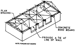
Fig.7.13
Wind Bracing for Roof Trusses
8.CONCLUSION
From
the recent cyclonic incidents it is evident that, cyclone shelter as a disaster
management measure is the most effective tool. But the existing cyclone shelters
in the coastal regions are not sufficient in number; they are not properly
located, designed and maintained. On the basis of the new concept of disaster
management, it is essential to consider a cyclone shelter not only as an
evacuation space for cyclone affected people during emergency period but also
as a community development centre throughout the whole year.
Disaster preparedness
and planning in the past have been too dependent on massive financial,
technical and infra-structural input by Government & NGO’s. While such
interventions are necessary, these steps must be accompanied by local people’s
participation as well as incorporating the age old wisdom of the people. This
will have the double advantage of empowering the people, drawing them into
plans which will no longer merely be injected from the outside, and will result
in a more thought out, user and environment friendly response to extreme
natural calamity.
However, it is
important to note that traditional houses can only be cyclone resistant with a
comprehensive approach for the implementation of all the recommendations in the
guidelines for cyclone resistant houses. The critical aspects of the recommendations
are a ) solving the social and environmental problems of housing, b) technology
input for improving and enhancing the durability of building material such as
bamboo, and c) careful consideration of the recommendations outlined in
construction techniques, structural components and details. In short the
cyclone resistant house is feasible with the simultaneous implementation of a
community approved plan of tree plantation, preservative treatment of all
components of building materials and following recommendations for technology
input in construction techniques and structural components and details.
REFERENCES
1.
Mahendran.k,
A.Zahir Hussain (2010) Disaster Resistant Rural House Design For Low Income
People ,INTERNATIONAL JOURNAL OF APPLIED ENGINEERING RESEARCH, Volume 1,
No1,77-82
2.
The
Practice and Reflection on Disaster Prevention Construction of Rural Dwelling
Houses in Coastal Typhoon Disaster Area;Pan Anping;College of Architectural and
Civil Engineering(Wenzhou University,Wenzhou, P.R.China,)
978-1-4244-6932-1110/$26.00 ©2010 IEEE
3.
The
Practice and Management on the Construction of Typhoon Emergency Shelter in
Coastal Rural Areas:Pan Anping:College of Architectural and Civil
Engineering(Wenzhou University,Wenzhou, P.R.China,) 978-1-4244-5326-9/10/$26.00
©2010 IEEE
4.
Ankush
Agarwal ( 2007) CYCLONE RESISTANT BUILDING Disaster Risk management
Programme
5.
Gujarat
State Disaster Management Authority (2001) Guidelines for Cyclone Resistant
Construction of Buildings in Gujarat
6.
Indian
Standard CODE OF PRACTICE
FOR DESIGN LOADS (OTHER THAN EARTHQUAKE) FOR BUILDINGS AND STRUCTURES,PART 3
WIND LOADS(Second Revision),Fifth Reprint JULY 1997,UDC 624·042·41,BUREAU OF
INDIAN STANDARDS,MANAK BHAVAN, 9 BAHADUR SHAH ZAFAR MARG,NEW DELHI 110002
LIST
OF REFERRED INDIAN STANDARDS
IS
No.
|
Title
|
800 : 1984
|
Code of practice for general
construction in steel (second revision)
|
875 (Part 3) : 1987
|
Code of practice for design loads
(other than earthquake) for buildings and structures: Part 3 Wind loads (second
revision)
|
13920 : 1993
|
Ductile detailing of reinforced
concrete structures subjected to seismic forces—Code of practice
|
Annexure
DESIGN
PROCEDURE FOR WIND RESISTANT BUILDINGS
The following procedure may be
followed to design a building that will be resistant to damages during high
winds/cyclones.
A.l Fix the Design Data
a. Identity the national wind zone in which the
building is situated. This can be seen from wind code (IS: 875 Part 3-1987) or
the Vulnerability Atlas of India (1997).
b. Corresponding to the zone, fix the basic design
wind speed, Vb which can be treated as constant upto the height of
10m.
c. Choose the risk co-efficient or the importance
factor k-|, for the building, as for example given below:
Building type Coefficient k1
i. Ordinary residential
building 1.0
ii. Important
building (e.g. hospital; 1.08 police station; telecommunication, school,
community and religious buildings, cyclone shelters, etc.
d. Choose
appropriate value of k2 corresponding to building height, type of
terrain and size of building structure, as per IS: 875 (part 3), 1987. For
buildings upto 10m height and category - A, which will cover the majority of
housing, the values are:
Terrain Coefficient kg
i. Flat sea-coastal area 1.05
ii. Level open ground 1.00
iii. Built-up suburban area 0.91
iv. Built-up
city area 0.80
e. The factor
k3, depends upon the topography of the area and its location above
sea level. It accounts for the acceleration of wind near crest of cliffs or
along ridge lines and deceleration in valleys etc.
A.2 Determine the wind forces
a. Determine the design wind velocity Vz and normal
design pressure Pz
Vz =Vbk1 k2
k3
Pz = 0.0006 Vz2
, Pz will be in kN/m2 for Vz in m/s
b. Corresponding to the building dimensions
(length, height, width), the shape in plan and elevation, the roof type and its
slopes as well as projections beyond the walls, determine the coefficients for
loads on all walls, roofs and projections, taking into consideration the
internal pressures based on size and location of openings. Hence calculate the
wind loads on the various elements nornnal to their surface.
c. Decide on the lines of resistance which will
indicate the bracing requirements in the planes of roof slopes, at eave level
in horizontal plane, and in the plane of walls. Then, determine the loads
generated on the following connections:
• Roof
cladding to Purlins
• Purlins to
rafters/trusses
•
Rafters/trusses to wall elements
• Between
long and cross walls
• Walls to footings.
A.3 Design
the elements and their connections
a. Load effects shall be determined considering all
critical combinations of dead load, live load and wind load. In the design of
elements, stress reversal under wind suctions should be given due
consideration. Members or flanges which are usually in tension under dead and
live loads may be subjected to compression under dead load and wind, requiring
consideration of buckling resistance in their design.
b. Even thin reinforced concrete slabs, say 75mm
thick, may be subjected to uplift under wind speeds of 55 m/s and larger,
requiring holding down by anchors at the edges, and reinforcement on top face!
As a guide, there should be extra dead load (like insulation, weathering
course, etc) on such roofs to increase the effective weight to about 375 kg/m .
d. Resistance to corrosion is a definite
requirement in cyclone prone sea coastal areas. Painting of steel structures by
corrosion-resistant paints must be adopted. In reinforced concrete
construction, a mix of M20 grade with increased cover to the reinforcement has
to be adopted. Low water cement ratio with densification by means of vibratos
will minimise corrosion.
e. All dynamically sensitive structures such as
chimney stacks, specially shaped water tanks, transmission line towers, etc.
should be designed following the dynamic design procedures given in various IS
codes.
f. The minimum dimensions of electrical poles and
their foundations can be chosen to achieve their fundamental frequency above
1.25 Hz so as to avoid large amplitude vibrations, and consequent structural
failure.
It may be emphasised that good
quality of design and construction is the single factor ensuring safety as well
as durability in the cyclone hazard prone areas. Hence ail building materials
and building techniques must follow the applicable Indian Standard Specifications.

No comments:
Post a Comment